In Industrial Automation, A Programmable Logic Controller Is A Ruggedized Computer
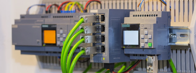 |
| Programmable Logic Controller |
Programmable Logic Controller (PLCs) are digital electronic devices that are widely used to
control industrial processes and machinery. They are designed to automate and
simplify the control of machines and processes by processing input signals from
sensors and other devices and providing output signals to actuators and other
control devices.
PLCs are commonly used in industrial automation applications
such as manufacturing, transportation, energy, and process control. They are
used to control processes such as assembly lines, robotic systems, packaging
machinery, conveyor systems, and other manufacturing equipment.
A typical Programmable
Logic Controller consists of three main components: a
CPU or central processing unit, input and output modules, and a programming
device. The CPU is the "brain" of the PLC and is responsible for
executing the control program that controls the machine or process. The input
and output modules are used to interface with the external world and provide
signals to the CPU. The programming device is used to create, edit, and
download the control program into the PLC.
PLCs are designed to be flexible and modular, allowing for
easy customization and expansion. They are often built on a modular design,
with input and output modules that can be added or removed as needed. This
modularity allows the PLC to be easily adapted to changes in the manufacturing process.
Programmable Logic Controllers are programmed using a special programming language called
ladder logic. Ladder logic is a graphical programming language that uses
symbols and diagrams to represent logic functions and operations. Ladder logic
programs are typically written using a computer software application that
allows the user to create and edit the program using a graphical interface.
Ladder logic programs consist of a series of
"rungs," with each rung representing a logical operation. Each rung
contains one or more "contacts" and "coils." Contacts
represent input signals, while coils represent output signals. The contacts and
coils are connected by logical operators such as "AND,"
"OR," and "NOT" to create logical expressions that control
the machine or process.


Comments
Post a Comment